
In a farm close to Magadi ( Karnataka) our customer Mr. Lohit Ramakrishnappa of Zolarified had installed a 5HP pump (with 3 phase AC induction motor) and Solar panels ( ~5kWp ) – it should have been an easy installation and commissioning. Only – none of the Solar MPPT drives (VFDs for running the motor using Solar energy) that Zolarified tried seemed to work in the installation. The Solar panels and the house for the drive were nearly 250 meters away from the location of the pump due to the terrain and the forest close to the farmland.
When we proposed our 5HP drive – we were confident that with some tweaks in Voltage and Current settings, we should be getting our drive working with the pump in no time. The wire cross section used for the length and max current output was ok. We set a higher Voltage output to compensate for the line loss. None of the settings seemed to work. The drive would almost immediately trip with a motor error. Did the long wires have a short or cut? No – all the three wires for the three-phase output were OK. Was the motor installed, OK? All the obvious candidates for the problem were eliminated one by one.
However, with the same 5 HP drive with the motor close by – there was no problem starting and running the motor. It was not the VFD issue either, or the settings for the 5HP motor.
Zolarified convinced the end customer to let us transport the long cable to our lab. When we connected our drive with the 5HP set up in the lab using the long wire, the possible reason for the issue presented itself.
Our engineers identified this as a transmission line effect. The square waveform from the output of VFD would have a frequency component of motor frequency (50Hz), its harmonics (100Hz, 150Hz, etc) along with PWM carrier frequency (10KHz) and its harmonics. Normally the inductance of the motor would filter out the PWM carrier frequency and the current would be at motor frequency. With the long transmission line having distributed impedance these components would undergo different phase delays by the time it reaches the motor. Hence the waveform at the terminal of the motor would not resemble the VFD output. The rise time of the VFD also plays an important role as it determines how the square wave harmonics get attenuated. The solution for this is to implement a filter to remove or significantly reduce the carrier amplitude and its harmonics using LC filter. Now the waveform will have a very small amplitude of frequency near and above PWM carrier frequency.
We built the filter and yes, the motor worked without any problem with the very same long cable between the motor and the VFD.
Image-1 shows the clean filtered wave form at the output of the VFD.
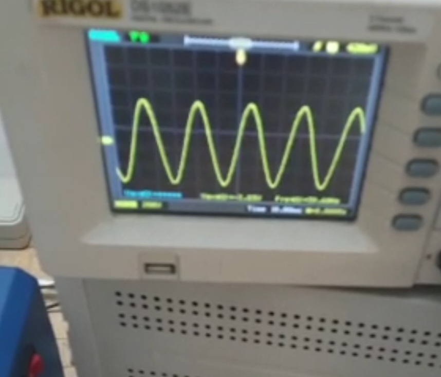
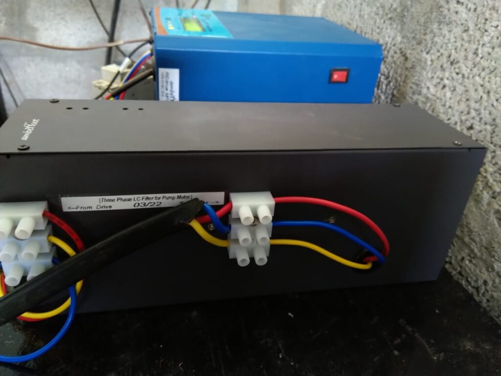
Image-2 shows the installed VFD with the LC filter packaged in an enclosure. Our engineers also built a circuit to draw power from the output of the VFD ( AC – ~ 450V) to power a 12V DC fan to keep the inductors and capacitors cool.
Thanks to Zoralified for being ready to do all-it-takes to solve the problem for their end customer and for trusting Amberroot to provide the solution.