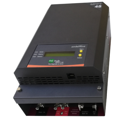
| REhub Variant | REhub MPPT 48 | REhub MPPT 36 | REhub MPPT 12/24 | REhub MPPT 12/24 | REhub MPPT Eco |
| Battery System Voltage | 48V | 36V | 36V | Auto detect 12/24V | Auto detect 12/24V |
| Recommended Solar module STC Wp | 1500Wp – 2700Wp | 1500Wp – 2000Wp | 600Wp – 1500Wp | 300Wp – 700Wp for 12V batt
300Wp – 1400Wp for 24V batt | 100Wp – 500Wp for 12V batt
300Wp – 1000Wp for 24V batt |
| Output Current – Continuous , Max | 40A | 40A | 35A | 50A | 25A |
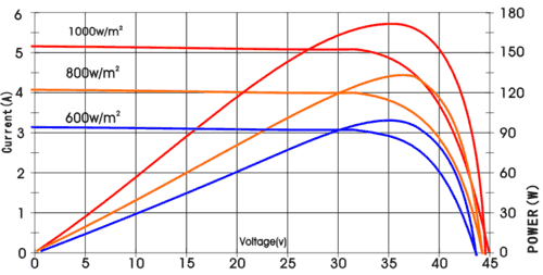
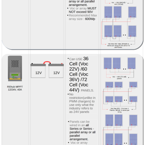
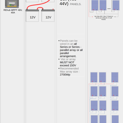
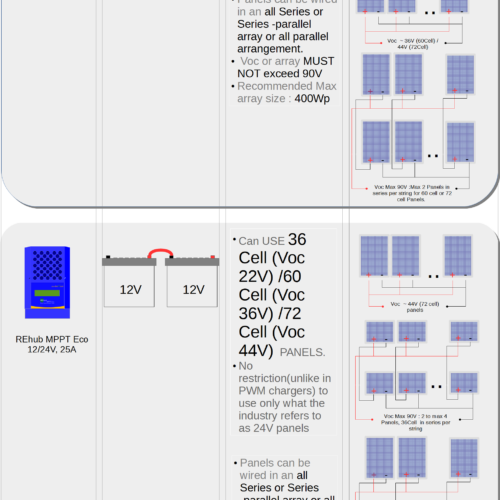
| PV Open Circuit Voltage (VOC) | 160V | 160V | 110V | 110V | 110V |
| PV MPPT Voltage range | > Batt V to 160V | > Batt V to 160V | > Batt V to 110V | > Batt V to 110V | > Batt V to 110V |
| Power Conversion Efficiency (typical) | 95% Typ | 95% Typ | 95% Typ | 95% Typ | 95% Typ |
| Full load output voltage | Same as battery voltage | Same as battery voltage | Same as battery voltage | Same as battery voltage | Same as battery voltage |
| Float Mode Charge Voltage (Factory Configurable) | 54V | 40.5V | 40.5V | 13.5V/27V | 13.5V/27V |
| Bulk Mode Charge Voltage (Factory Configurable) | 57.6V | 43.2V | 43.2V | 14.4V/28.8V | 14.4V/28.8V |
| Ambient temperature range | '-10°C to 50°C | '-10°C to 50°C | '-10°C to 50°C | '-10°C to 50°C | '-10°C to 50°C |
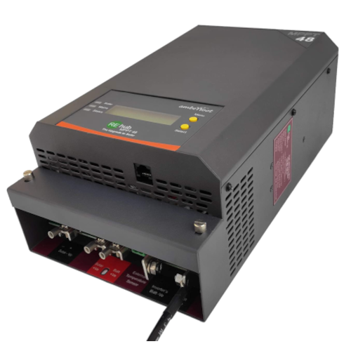
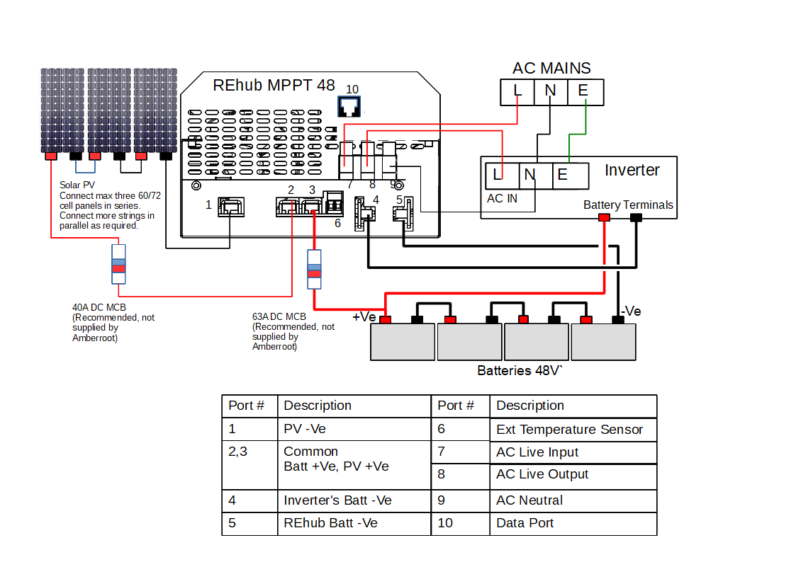
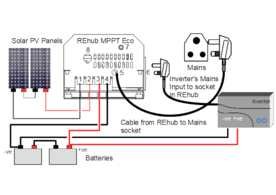
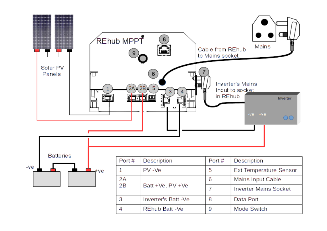
| Ports | 1 PV -Ve input
1 PV +Ve Input
1 +Ve BatteryTerminal output
1 -Ve terminal for current monitoring
1 -Ve Battery Terminal output
1 Numbers of 3 Port AC Terminal for Input and Output AC Live and Neutral
1 External Temperature Sensor connector
1 RS485 Port | 1 PV -Ve input
1 PV +Ve Input
1 +Ve BatteryTerminal output
1 -Ve terminal for current monitoring
1 -Ve Battery Terminal output
1 Numbers of 3 Port AC Terminal for Input and Output AC Live and Neutral
1 External Temperature Sensor connector
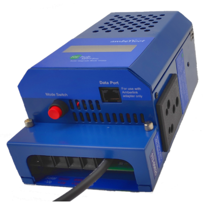
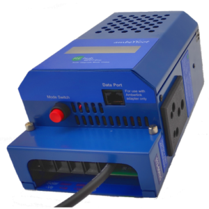
1 MODBUS - RS485 Port ( RJ45 Interface) | 1 PV -Ve input
1 PV +Ve Input
1 +Ve BatteryTerminal output
1 -Ve terminal for current monitoring
1 -Ve Battery Terminal output
1 Numbers of 3 Port AC Terminal for Input and Output AC Live and Neutral
1 External Temperature Sensor connector
1 MODBUS - RS485 Port ( RJ45 Interface) | 1 PV -Ve input
1 PV +Ve Input
1 +Ve BatteryTerminal output
1 -Ve terminal for current monitoring
1 -Ve Battery Terminal output
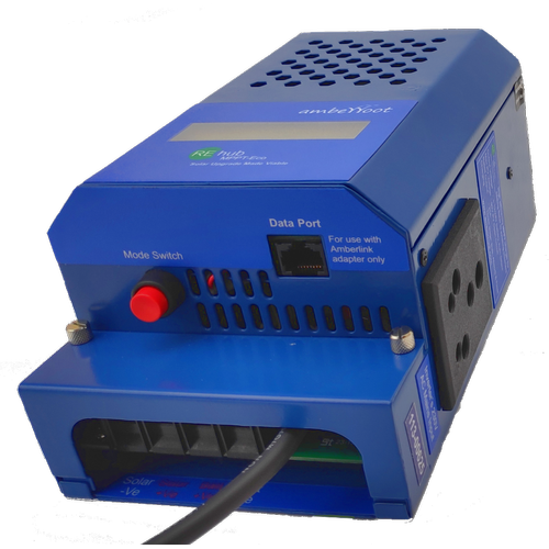
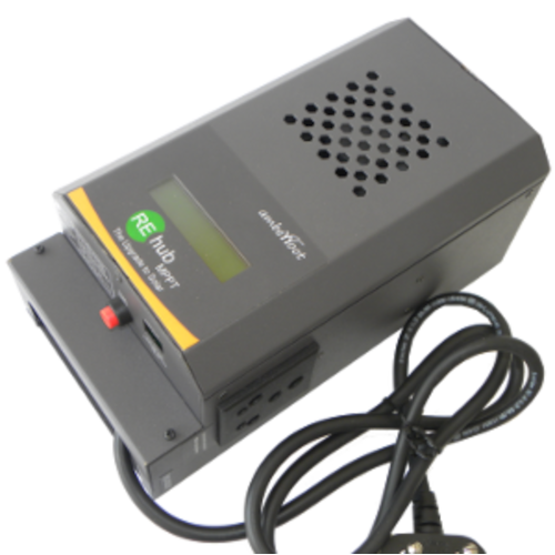
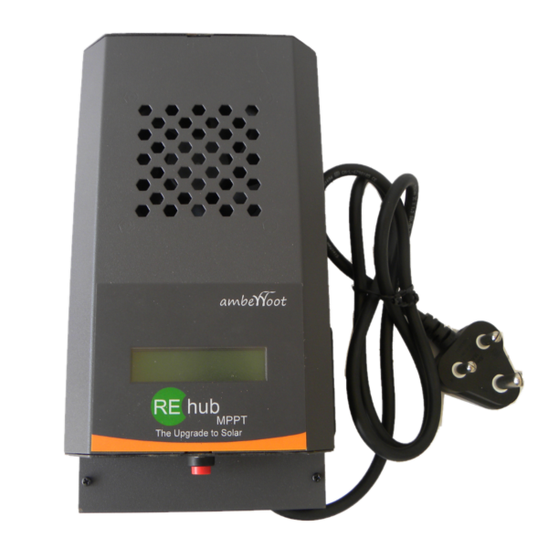
1 15A and 6A 3 Pin Socket
1 15A 1 Meter long wire with 3 Pin Plug
1 MODBUS - RS485 Port ( RJ45 Interface) | 1PV -Ve input
1PV +Ve input
1Battery -Ve Input
1Battery +Ve
1 15A and 6A 3 Pin Socket
1 6A 1 Meter long wire with 3 Pin Plug
1 MODBUS - RS485 Port ( RJ45 Interface) |
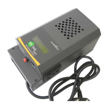
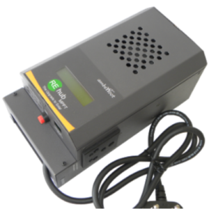
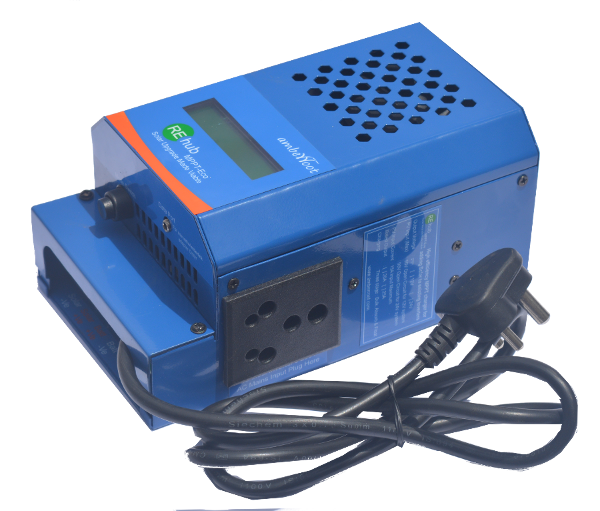
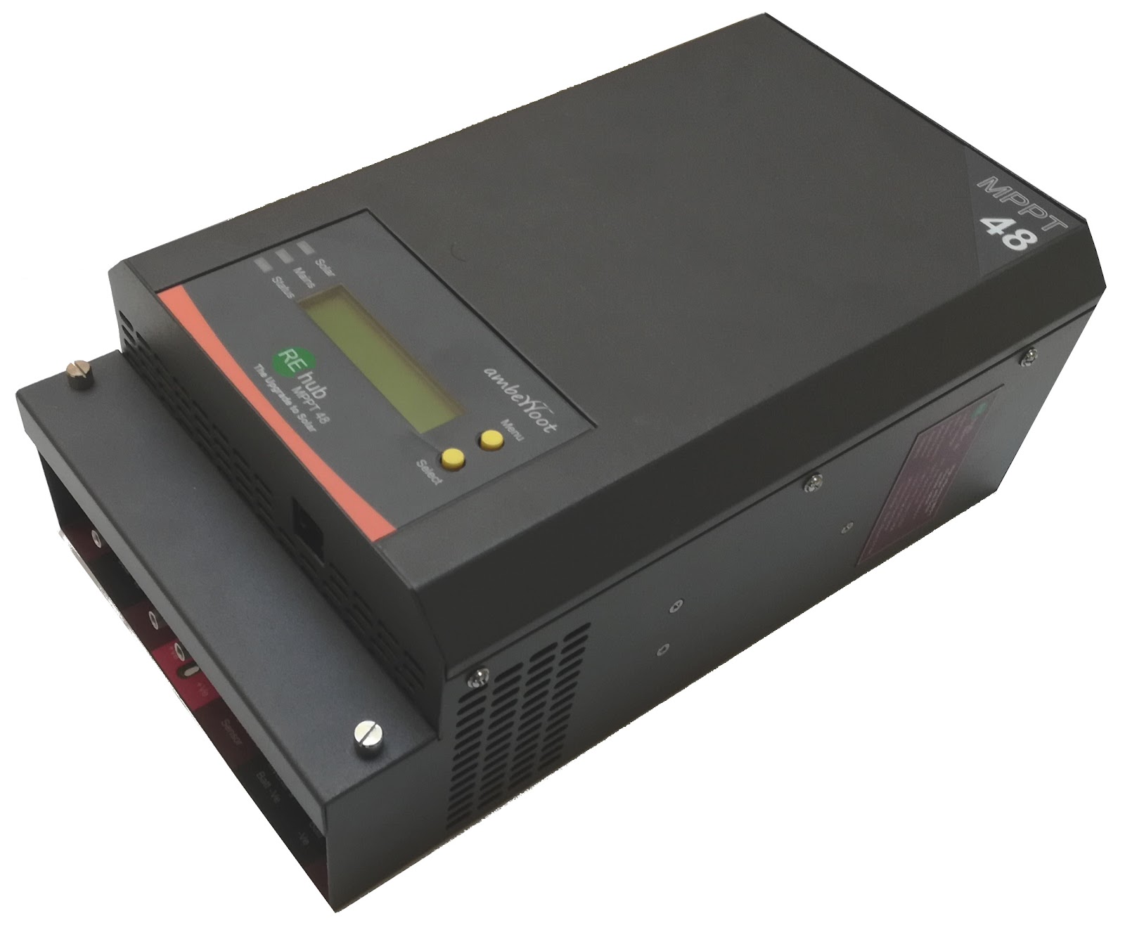
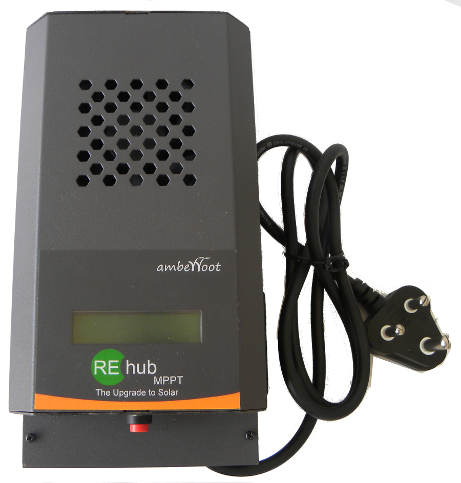
| Display | 16 X2 Backlit character LCD to display system state, Instantaneous Power and cumulative energy generated from Solar PV | 16 X2 Backlit character LCD to display system state, Instantaneous Power and cumulative energy generated from Solar PV | 16 X2 Backlit character LCD to display system state, Instantaneous Power and cumulative energy generated from Solar PV | 16 X2 Backlit character LCD to display system state, Instantaneous Power and cumulative energy generated from Solar PV | 16 X2 Backlit character LCD to display system state, Instantaneous Power and cumulative energy generated from Solar PV |
| Dimension | 307X182X107mm | 307X182X107mm | 253X134X106mm | 253X134X106mm | 200X120X95mm |
| Modes | Auto (Solar à Mains à Battery)
Offgrid (Solar à Battery à Mains)
On1Day/OnAlways ( Mains + Solar ) | Auto (Solar à Mains à Battery)
Offgrid (Solar à Battery à Mains)
On1Day/OnAlways ( Mains + Solar ) | Auto (Solar à Mains à Battery)
Offgrid (Solar à Battery à Mains)
On1Day/OnAlways ( Mains + Solar ) | Auto (Solar à Mains à Battery)
Offgrid (Solar à Battery à Mains)
On1Day/OnAlways ( Mains + Solar ) | Auto (Solar à Mains à Battery)
Offgrid (Solar à Battery à Mains)
On1Day/OnAlways ( Mains + Solar ) |
| Changing Modes | Mode and Select Switch to navigate through an heirarchical Menu | Mode and Select Switch to navigate through an heirarchical Menu | Press and Hold Mode Switch, Release to Select Mode Option | Press and Hold Mode Switch, Release to Select Mode Option | Press and Hold Mode Switch, Release to Select Mode Option |
| Weight | ~4 Kgs | ~4 Kgs | ~3 Kgs | ~3 Kgs | ~2 Kgs |
| Cooling | 2 Fans, PWM controlled based on Temperature | 2 Fans, PWM controlled based on Temperature | 1 Fans, PWM controlled based on Temperature | 1 Fans, PWM controlled based on Temperature | 1 Fans, PWM controlled based on Temperature |
| Battery Reverse polarity protection | Electronically protected | Electronically protected | Electronically protected | Electronically protected | Electronically protected |
| PV Reverse and Short circuit protection | Electronically protected | Electronically protected | Electronically protected | Electronically protected | Electronically protected |
| Over current protection protection | System shutdown, recovers with a timeout | System shutdown, recovers with a timeout | System shutdown, recovers with a timeout | System shutdown, recovers with a timeout | System shutdown, recovers with a timeout |
| Over temperature protection protection | System shutdown, recovers with a timeout | System shutdown, recovers with a timeout | System shutdown, recovers with a timeout | System shutdown, recovers with a timeout | System shutdown, recovers with a timeout |